device output waveform is a fixed 50% duty cycle (the pro-
grammed quiescent duty cycle value) regardless of the applied
external magnetic field. After powering-up, the A1354 outputs
its quiescent duty cycle waveform for 800 ms, regardless of the
applied magnetic field (see figure 9). This allows the BCM to
compare the measured quiescent duty cycle with an ideal 50%
duty cycle.
After the initial 800 ms has elapsed, the duty cycle corresponds to
an applied magnetic field as expected. The 800 ms calibration test
time corresponds to a PWM frequency of 125 Hz. If the PWM
frequency is programmed away from its target of 125 Hz, the
duration of the calibration test time will scale inversely with the
change in PWM frequency.
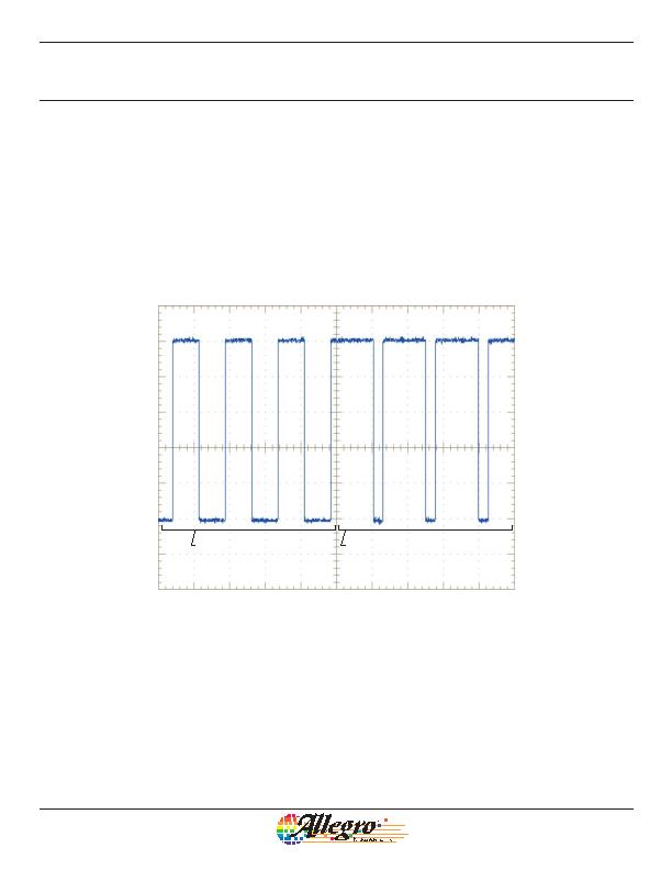
Figure 9. Calibration Test Mode. After powering-on, the A1354 outputs a 50% duty cycle for
the first 800 ms, regardless of the applied magnetic field (Calibration Test mode in effect).
After the initial 800 ms has elapsed, the output responds to a magnetic field as expected.
The example in this figure assumes that a large +B (south polarity) field is applied to the
device after the initial 800 ms.
During Calibration Teat mode
PMW output = 50% duty cycle
After the calibration expires, PWM output
proportional to external magnetic field
High Precision 2-Wire Linear Hall Effect Sensor IC
with Pulse Width Modulated Output
A1354
21
Allegro MicroSystems, Inc.
115 Northeast Cutoff
Worcester, Massachusetts 01615-0036 U.S.A.
1.508.853.5000; www.allegromicro.com
发布紧急采购,3分钟左右您将得到回复。
相关PDF资料
A1356LKB-T
IC SENSOR HALL EFFECT 3 SIP
A1361LKTTN-T
IC HALL EFFECT SENSOR LN 4-SIP
A1374EKB-T
IC SENSOR HALL EFFECT PREC 3-SIP
A1422LK
IC SENSOR HALL EFFECT AC 4-SIP
A1425LK
IC SENSOR HALL EFFECT AC 4-SIP
A1645LK-I2
IC SENSOR HALL EFFECT AC 4-SIP
A3230LUA-T
IC SW HALL EFFECT CHOPPER 3-SIP
A3241LUA-T
IC SWITCH HALL EFFECT 3-SIP
相关代理商/技术参数
A1354KKTTN-T
功能描述:IC HALL EFFECT SENSOR 2WIRE 4SIP RoHS:是 类别:传感器,转换器 >> 磁性 - 霍尔效应,数字式开关,线性,罗盘 (IC) 系列:- 标准包装:1 系列:- 传感范围:20mT ~ 80mT 类型:旋转 电源电压:4.5 V ~ 5.5 V 电流 - 电源:15mA 电流 - 输出(最大):- 输出类型:数字式,PWM,8.5 位串行 特点:可编程 工作温度:-40°C ~ 150°C 封装/外壳:20-SSOP(0.209",5.30mm 宽) 供应商设备封装:20-SSOP 包装:Digi-Reel® 其它名称:AS5132-HSST-500DKR
A1354P1-2
制造商:APEM 功能描述:
A1354P1-6
功能描述:SWITCH HARDWARE RoHS:是 类别:开关 >> 配件 系列:- 标准包装:100 系列:- 其它名称:886.0007886.0007-ND
A1354P2-4
制造商:APEM 功能描述:
A1354P2-5
功能描述:SWITCH HARDWARE RoHS:是 类别:开关 >> 配件 系列:- 标准包装:100 系列:- 其它名称:886.0007886.0007-ND
A1355P1-2
制造商:APEM 功能描述:
A1355P1-3
制造商:APEM 功能描述:
A1355P1-8
制造商:APEM 功能描述:
